Opto-Isolated PWM Motor Driver
Discrete opto-isolated low-side driver for a small brushed-DC ducted fan — the first hardware stage of the icarus-fc 1D hover stabilizer, built on a solderboard and validated open-loop on the bench before MCU integration.
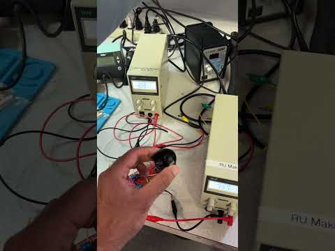
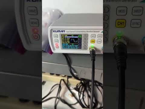
Driver running open-loop with the ducted fan — click to watch (YouTube Shorts)
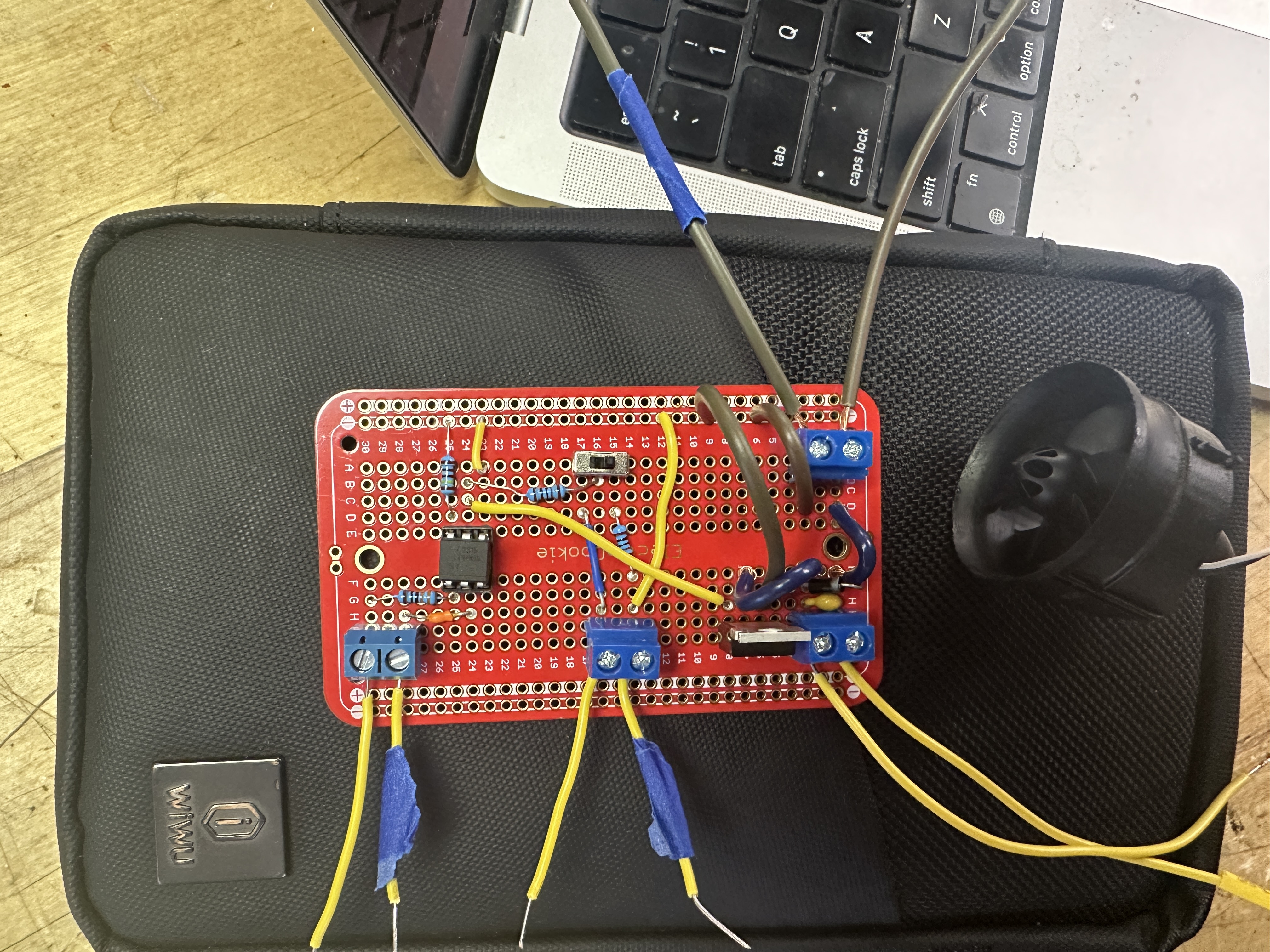
Overview of circuit
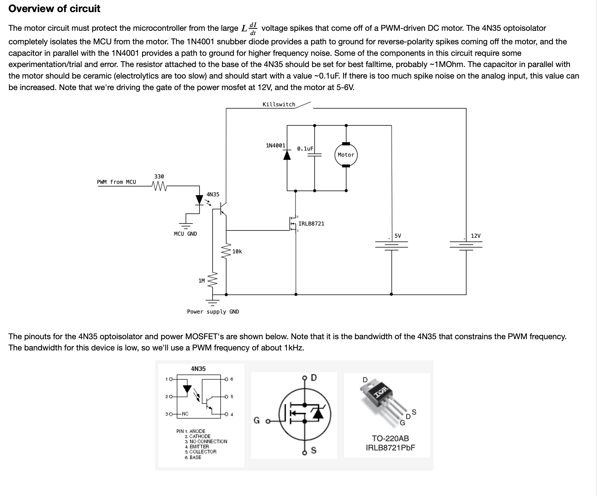
The motor circuit must protect the microcontroller from the large L · di/dt voltage spikes that come off a PWM-driven DC motor. The 4N35 optoisolator completely isolates the MCU from the motor. The 1N4001 snubber diode provides a path to ground for reverse-polarity spikes coming off the motor, and the capacitor in parallel with the 1N4001 provides a path to ground for higher-frequency noise.
Some of the components in this circuit require some experimentation/trial and error. The resistor attached to the base of the 4N35 should be set for best fall-time, probably ~1 MΩ. The capacitor in parallel with the motor should be ceramic (electrolytics are too slow) and should start with a value ~0.1 µF. If there is too much spike noise on the analog input, this value can be increased.
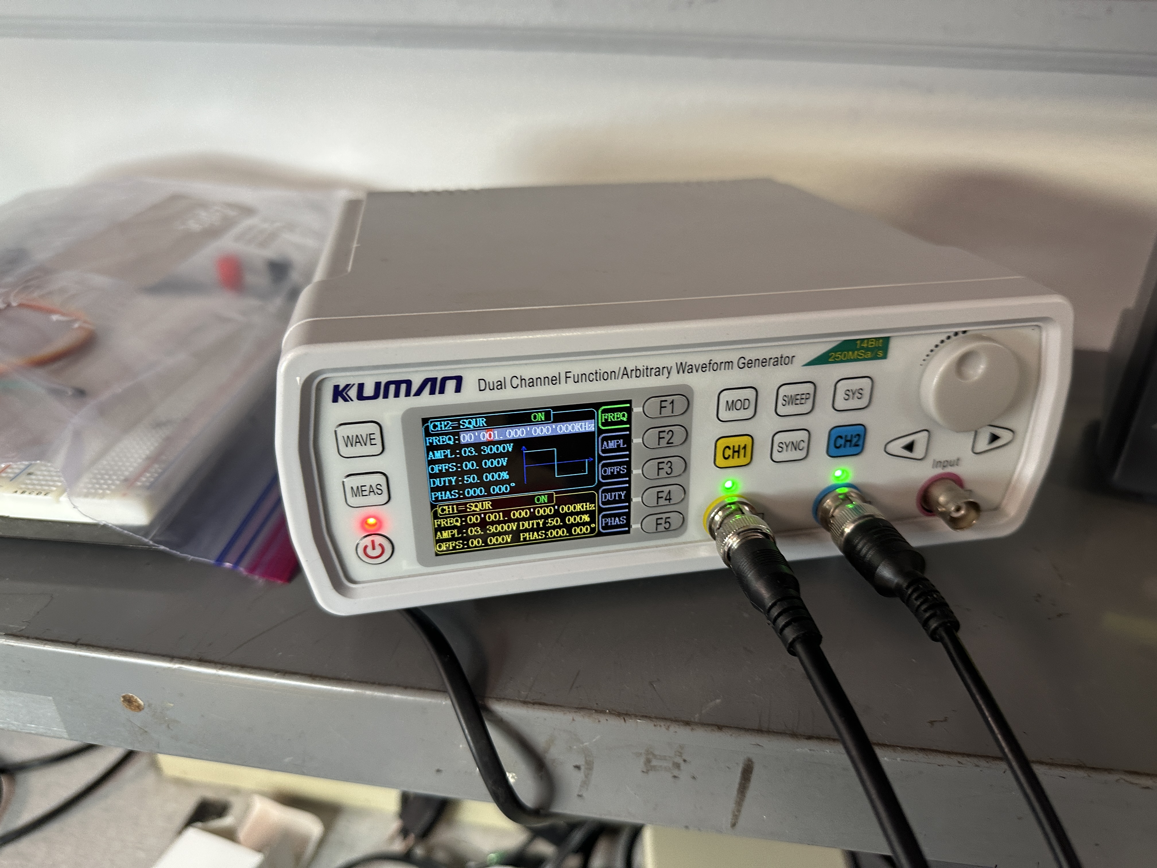
Note that we’re driving the gate of the power MOSFET at 12 V, and the motor at 5–6 V.
Pinouts and PWM frequency
The pinouts for the 4N35 optoisolator and the IRLB8721 power MOSFET (TO-220AB package) are shown in the schematic above. Note that it is the bandwidth of the 4N35 that constrains the PWM frequency — the bandwidth for this device is low, so the design uses a PWM frequency of about 1 kHz.
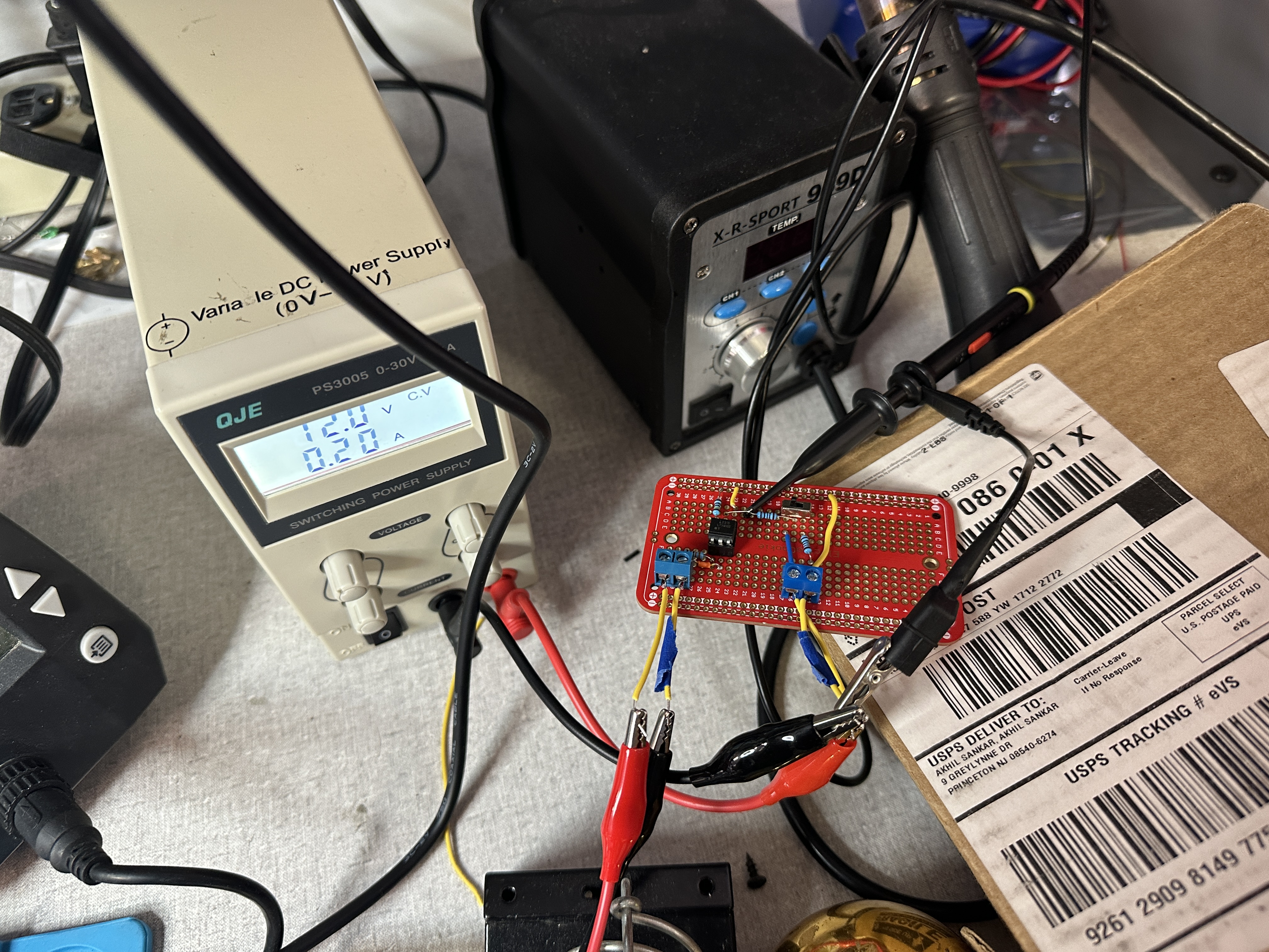
Bench setup
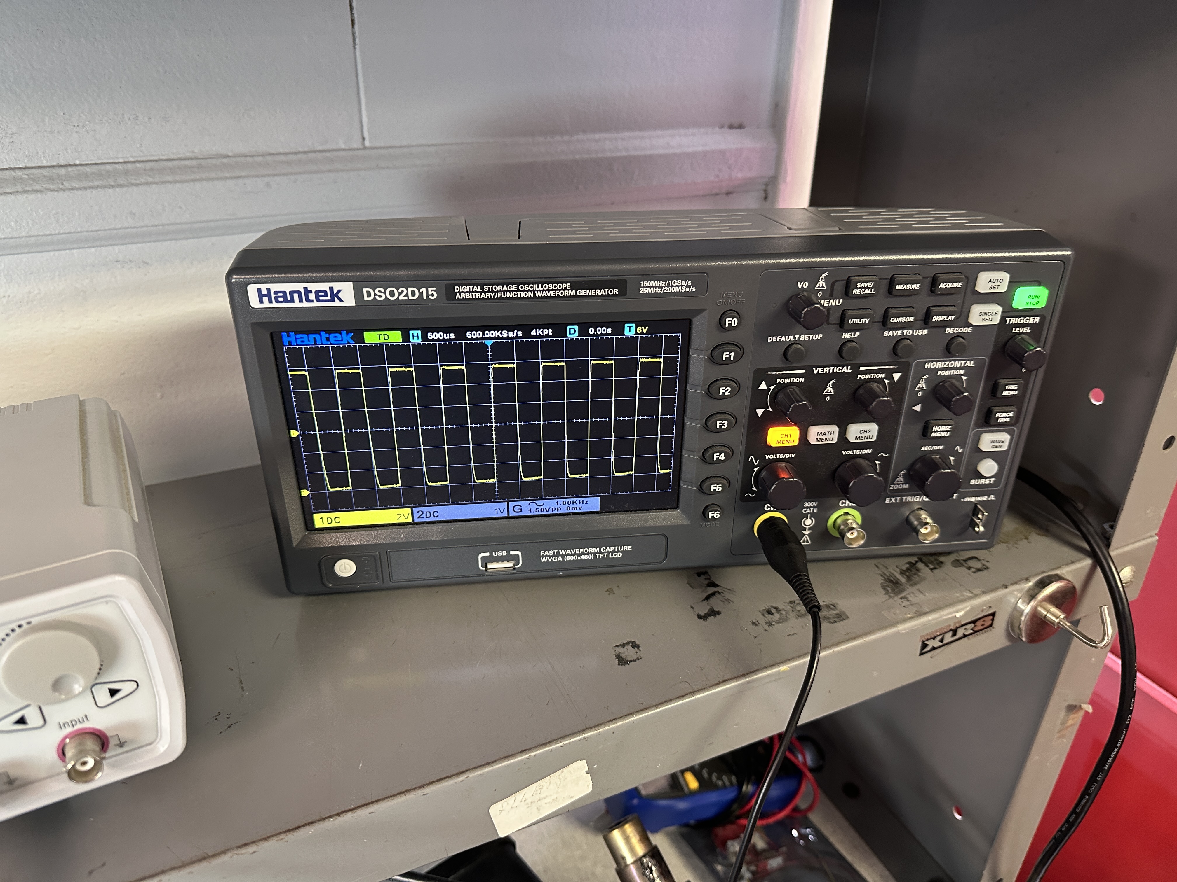
A function generator stands in for the MCU’s PWM output during open-loop validation; the oscilloscope probes the input PWM and the gate-drive node downstream of the optoisolator.
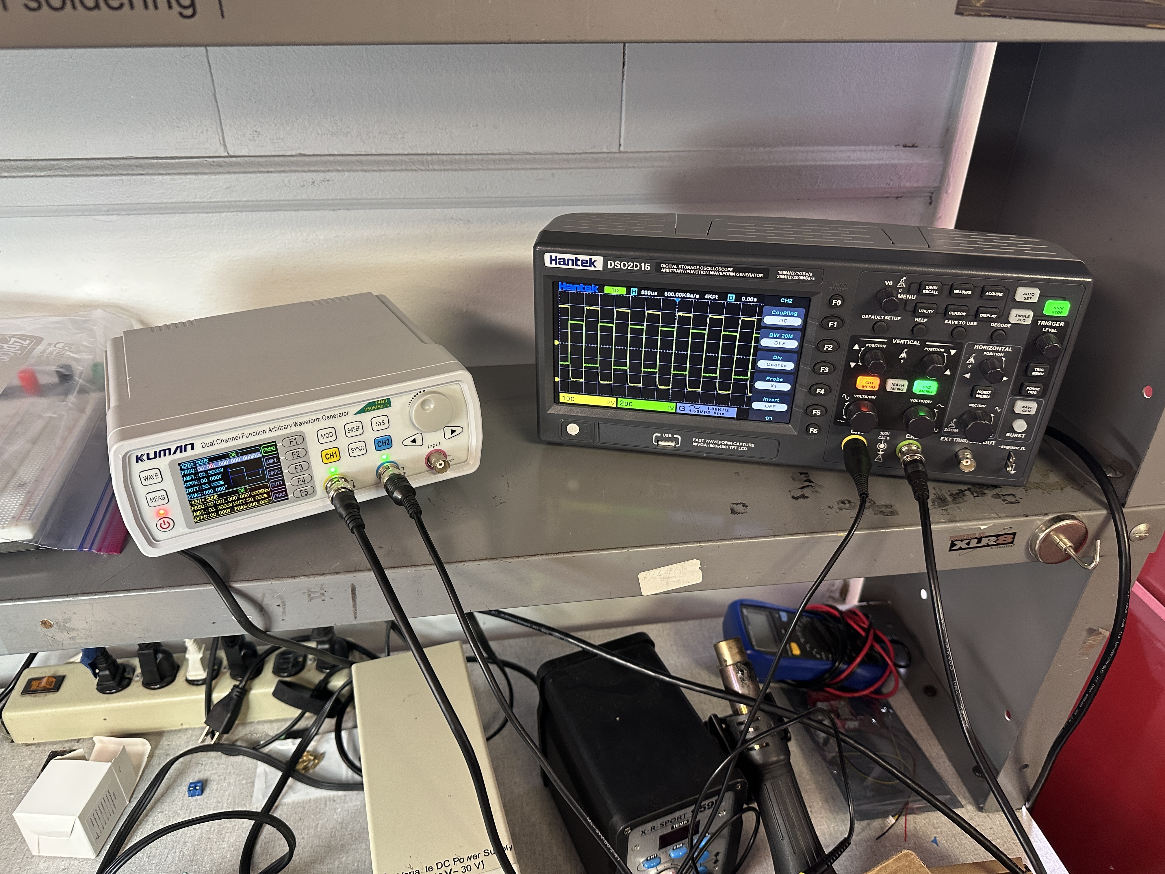
Waveforms
Source files
- Schematic and design notes:
1d_stabilizer/notes/motor_control_circuit.png - Bench-test photos:
1d_stabilizer/results/open_loop_testing/ - Reference reading: DC motor circuit layout, PWM (Pico), brushed DC principles